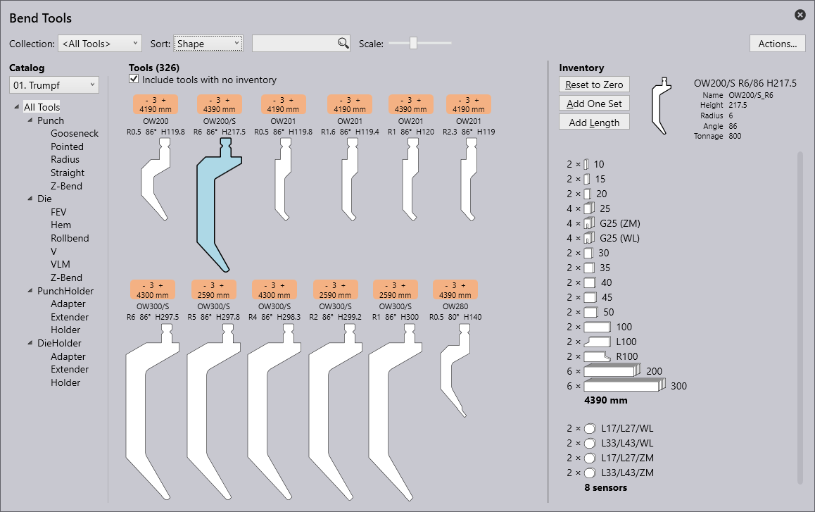
Flux Reference Manual

  • Welcome to Flux
  • Introduction
    • Installing the Software
    • The User Interface
    • Part Workflow
    • The Machine Database
  • Cut
    • Basic Workflows
      • Part Workflow
        • Load Part
        • Sketch Mode
        • Measure
        • Modifying Laser Part
        • Nesting
        • Sequence Navigator
        • NC Code Generation
      • Job workflow
        • Create Job
        • Set Laser Technology Table (LTT)
        • Nesting
        • Automatic Part Placement
        • Manual Part Placement
    • Advanced Topics
      • Geometry Import Options
      • Advanced Tooling Options
        • Editing Microjoints
        • TwinLine
        • FlyLine
        • Dimple Approach
        • Remainder Sheets
        • Pie-Slug Circular Holes
        • Avoid Retooling Pierces
        • Finishing Rules
        • Clone LTT
      • Advanced Nesting Features
        • Mirrored Parts
        • Find a Part in Nest Layout
        • Filler parts in Nest Layout
      • Advanced Tooling Optimization
        • Contour Quality
        • Optimizing Stability with Scrap Cutting
        • Optimizing Tilting Behaviour
        • Space Out Slice Cuts to Avoid Collision
        • Minimize Number of Different Layouts
        • Dynamic Level Setting
      • Advanced Menu Options
        • Context Sensitive Menus
        • Hierarchy of Settings
        • Multi-Selections
        • CSV Output
      • Manual Sheet Slicing Cuts
      • Text on Parts
    • Application Settings
      • Cut CAM
        • Layout
          • Nest Settings
          • Sheet
          • Sheet Handling
          • Skeleton Cuts
          • Work Support
        • Laser CAM
          • Sequence
      • Cut Outputs
      • Cut View
  • Bend
    • Basic Steps of Flux Bend
    • Basic Workflow
      • The Main Panel
      • The Workflow Panel
      • Batch processing
      • Modifying the Geometry
      • The Bend Navigator
      • Editing the Bend Solution
        • Editing a Bend
        • Changing the Bending Sequence
        • Editing a Tool Mount
        • Editing a Bend Setup
        • Editing the Back-Gauges
        • Angle Measurement
        • Using a Pre-Bend
        • Editing multiple mounts
        • Adding a Tooling station
      • Recomputing the Bend Solution
      • Generating Bend Outputs
      • Export Bend Report
    • Design of bend parts
      • Min Radius and Flange Length
      • Corner Design
      • Bending Tolerances
      • Selection of Tools
    • Advanced Workflow
      • Preparation of Bend Parts
        • Preparing a 2D drawing
        • Editing a Drawing
        • Add Bending Information as Text to DXF
        • Measuring and changing Outer Dimension
        • Preparing 3D models
        • Preparing an Assembly
        • Component Detection
        • Form Detection
      • Edit Tools
        • Changing Tool Map
        • Change Tool Segmentation
        • Editing Tool-mount Segments
        • Adding a Gap into the Tool
        • Use a Double-V Adapter
        • Tool Priority
        • Creating a Tool
      • Using Bend Deductions
      • Control Visibility
      • Comment Section in Bend Panel
      • Tools/Machine Tonnage Check
    • Settings
      • Application Settings
        • Bend CAM
          • Bend Outputs
          • Bend View
          • Bend Cell
      • Database Settings
        • Materials
        • Machines
        • Bend Tools
        • Bend Deductions
        • Bend grippers
        • Forms/Components
      • Bend Settings
      • Machine Defaults
  • Robotic Bending
    • Overview of Robotic Bending
    • Basic Steps of Robotic Bending
    • Workflow
      • Part Pickup
        • Pickup from a Pallet
        • Pickup from a Dispenser
      • Insertion Strategy
      • Bending Strategy
      • Regripping (RG) Stations
        • Re-Grip Stations
        • Methods of Regripping
        • Adding ReGrip
        • Modify ReGrip Position
        • Remove ReGripping
        • Regrip with a Jaw Gripper
        • Gripper Panel & Suction Panel
      • Extraction Strategy
      • Part Deposit
        • Adapt Part Deposit
        • Adding Parts & Stacks
          • Deposit Panel
          • Add Separator Sheets
          • Lock Part-Rest
          • Repeat Grid Field
          • Deposit Sequence
        • Deposit Pattern Types
      • Waypoints
        • Adapt WayPoints
        • Display Waypoints
        • Simulate Waypoints
        • Modify WayPoints
        • Properties of Waypoints
    • Advanced Topics
      • Cell Configuration
        • Track Setup
        • Gripper Inventory
        • BendCell settings
      • Gripper Configuration
        • Create/ Edit a Gripper
        • Import Gripper from DXF
    • Troubleshooting Bend Errors
      • Part Pickup Error
      • Collisions with Machine
      • Overtravel of Axis
      • Modifications of Waypoints
      • Collisions while Insertion and Extraction
  • Fold
    • Switching to Fold CAM
    • The Fold View
    • Editing Operations
      • Editing a Bend-Op
      • Editing a Side/Section
      • Changing the Sequence
      • Editing the Blank-holders
      • Editing the Gauging
      • Editing the Blades
      • Editing the Loading
      • Editing the Unloading
    • Tool Management
    • Fold CAM Summary
  • Generic Application Settings
    • Drawing
      • Layers
      • Dimensions
      • View
    • Environment
    • Import/Export
  • Flux Reports
    • Report Designer
    • Fields, Pictures and Tables
    • Bands (sub-reports)
    • Labels, Bitmaps and Shapes
  • Appendix
    • Supported 3D Formats
    • Separator Sheet DXF
Bend
/
Settings
/
Database Settings
/
Bend Tools

Bend Tools

All the available tools are displayed in the inventory of tools.

New tools can also be added in bend tools.

newitem384
No Description Meaning

1

Tool lists

The tool lists to be worked with can be selected hereNew tool lists can be created with the option New.

2

Sort

The tools can be sorted according to specific criteria here (height, name, shape, radius, angle, die width, priority, tool management). Tools can be searched for using the search bar. Here, for example, an alphabetic search can be made for names of tools. Additionally, more complex search requests can be made. This search request finds all tools with UT or EV in the name which also meet the following conditions: angle≤30, height≥140, height≤220, radius=1.

3

Scale

The size of the view of the tools can be changed with the slide.

4

Save

Saves the tool list.

5

Actions

The following actions can be performed:

- A Create tool list: A new tool list is created.

- B Copy tool list: An available tool list is copied.

- C Reset tool list: The number of tools in the current tool list is set to 0.

- D Export tool list: The current tool list can be exported as a ".btools" file.

- E Import tool list: A tool list can be imported as ".btools".

- Import F ARV: A tool can be imported from an ARV fileThese tools are then custom filed in the tool catalog (this will be recreated if it was not available beforehand).

- Import G DXF: A tool can be imported from a DXF file. These tools are then custom filed in the tool catalog (this will be recreated if it was not available beforehand).

- Export F ARV: A selected tool can be exported as an ARV file.

- Export G DXF: A selected tool can be exported as a DXF file.

- Cancel H: Closes the "Actions…​" window.

6

Tool management

Shows an overview of the selected tool. The following actions can be performed:

- Reset to zero: The total inventory of the selected tool is removed from the current tool list.

- Add a block: Adds a block of the selected tool to the current tool list.

- Add tool length: Custom tool lengths can be added to the selected tool.

- Add All: The complete inventory of the selected tool is loaded in the current tool list. The inventory is defined in the <All tools> tool list.

7

Tool inventory

Displays the inventory of the selected tool. Left mouse-click to add a segment and right click to remove.

8

Tool without inventory

A tool without inventory is not included in the current tool list. By clicking on the empty field a standard inventory for the tool is added and the tool is incorporated into the current tool list.

9

Tool with inventory

1 = High priority

5 = Low priority

10

Tool display area

In the tool display area, all tools from the selected tool list are displayed. Tools without inventory can also be displayed with the checkbox "Include tools without inventory".

11

Tool filter

Here, the tools of the current tool list are structured according to their type and shape. Selecting an element in this structure enables filtering.

12

Catalog

One of the many tool catalogs installed can be selected with this (including TRUMPF, custom, etc.).

13

Filter condition

The filter condition for the current tool list, which is automatically used by the auto-tooler. This can be used for a named tool list, but not for the special list <All tools>. It is possible to filter according to various aspects, including machine, material, sheet thickness, etc.

Machines Bend Deductions

      Copyright © 2023 by Metamation. All rights reserved.

    Compiled by Bento